What's WindChallenger Project
| Abstract of the Project | R&D of Rigid Sail | R&D of Ship | R&D of Optimum Routing |
1. R&D of Rigid Sail
Towards the low carbon society, it is necessary for ship's operations to reduce CO2. The technologies and developments for this purpose become an important global subject. In order to realize the demand, WCP (Wind Challenger Project) started in the University of Tokyo from Oct. 2009 as the industry-university joint research, and has been developing a huge rigid sail system that can successfully catch the wind energy at sea.
・The 1st research program (Sep., 2009 - Sep., 2014)
The research budget during this term was about 170 million yen through three years. The half of the budget was the fund by "the research scheme which met the industry request" of Class NK, and the remainder provided from five private companies (Nippon Yusen, Mitsui O.S.K.Lines, Kawasaki Kisen, Oshima shipyard and TADANO).
As the 1st design ship, a large-sized cargo ship (180,000 DWT cape size bulk carrier) equipping 9 large rigid sails (1 sail is 50m x 20m=1,000m2) on board was investigated, and its feasibility research about technical, economical, and regulation matters are clarified. For the beam wind (wind velocity about 12 m/s), these sails can achieve 14 knot sea speed without engine power. In a real ocean voyage (Japan / North America west coast route) using both engine power and sails, it has been confirmed by the simulations that the fuel consumption is reduced about 30% per year.
From Oct., 2011, the research proceeded to the actual sail design and construction stage. The large sail model (1 / 2 scale model: 25m x 10m) was constructed on the top of the hill close to Sasebo in winter 2013, and the strength, aerodynamic data were obtained against various weather condition.
・The 2nd research program (Nov., 2013 - Mar., 2016)
The budget during this term was supported by the grant of The Ministry of Land, Infrastructure and Transport as well as the support of Class NK and 3 private companies (Nippon Yusen, Mitsui O.S.K.Lines and TADANO).
In the 2nd research stage, design and operating method have been researched with the sail equipped large-size merchant ships. EPP (Energy Prediction Program) and WCSS(Wind Challenger Sailing Simulation) which were developed in the 1st stage have been improving, and the design and ship-operation method have been developing. Particularly, the shipping method for using global winds, such as the optimal routing against the trade winds and westerlies, serves as development of a new shipping business model.
・The 3rd research program (Oct., 2014 - Sep., 2017)
While performing the analysis of a large-scale sail model test in the 1st research stage and establishing the construction method of a real large sail, examination and development of concrete design have been executing. Also, the compliance of rule and safety performance "HAZARD" is checking designing the new type auto pilot.
After clearing these subjects during the 2015, the detail design of a real sail equipped ship will be finished in 2016. The service of the 1st ship will be aimed at in 2017.
。
![]()
2. R&D of Rigid Sail
 The WCP's sail can be folded by the powered sliding mast. Dimension of the typical sail is 50m in height, 20 m in width, and 1,000m2 area, in full-expanded condition. The wings section of the sail is important in the performance of a sail, the pressure side is adopted the hollow-shaped wing section with a camber (upper left figure) from the consideration of a synthetic examination for the various wind direction. Thickness ratio is adopted as 0.2, which can make the stall angle larger. The material of the sail is GFRP (glass fiber strengthening plastic) or aluminium alloy. Although weight of rigid sail changes with materials, it is about 40t, and the weight of sliding mast is about 60t.
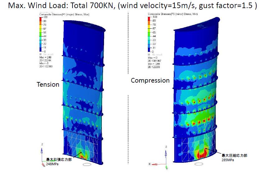
Predicted Stress distribution at maximum wind load 700kN (wind velocity 15 m/s, gust coefficient 1.5) by FEM analysis. The maximum tensile stress (tension side) becomes 248MPa, and the maximum compression stress (compression side) 285MPa.
3. R&D of Ship
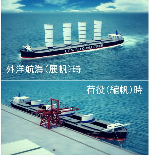 The 1st ship-plan of window challenger project was 180,000 DWT cape size bulk carrier (in detail here). The 2nd plan is 84,000 DWT Pana-Max type bulk carrier considering that the shipper and the service route is almost fixed, which makes easier for designing.
In this plan, 4 rigid sails are installed in the space between each hatch. Fore bridge is adopted in order to make the front view clear.
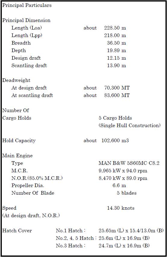
(Principal dimension, General arrangement of this ship)
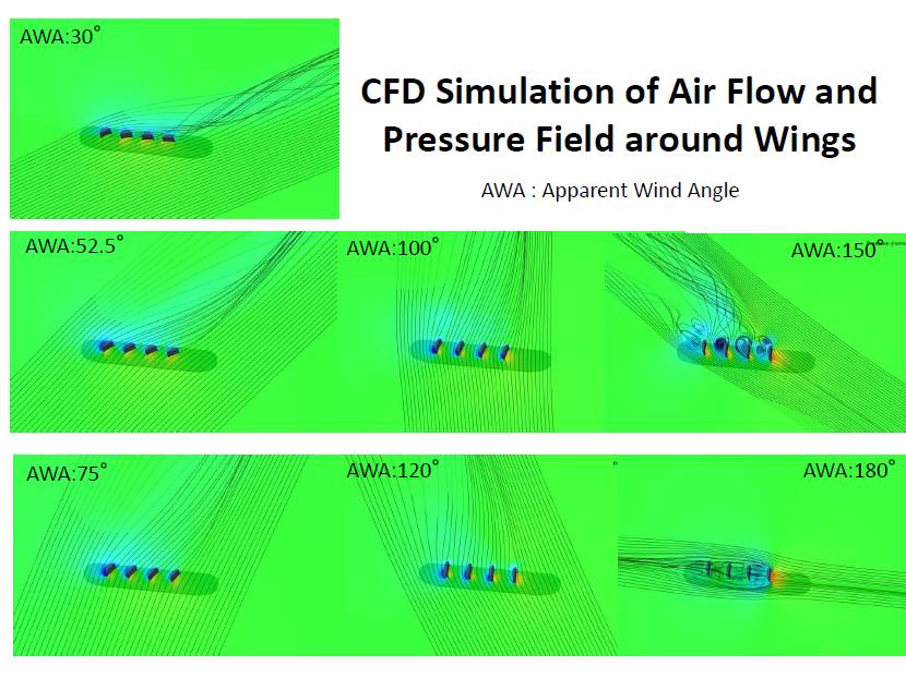
Aerodynamic performance estimated by CFD (Computational Fluid Dynamics) is shown in right hand side figure, which realize the streamline and pressure distribution to each wind direction. For head wind, it is found that 4 sails are working as one sail on the whole, and lift force are mainly generated by front side 3 sails. In beam wind, every 4 sails make almost the same lift force. In following wind condition, the stream is separating from sail body and introduces the drag force, which makes the ship propulsion force.
 In this research, EPP (Energy Prediction Program) has been developed, by which the energy saving is easily predicted for various true wind speed and direction. Using this program, the decreasing rate of the fuel consumption induced by the sails can be predicted against the wind velocity and direction as shown in the upper figure, where TWS is true wind velocity (True Wind Speed) and TWA is a true wind direction (True Wind Angle). From this figure, it is found that the energy-saving becomes the maximum around the beam wind.
4. R&D of Optimum Routing
 For the conventional ships, it is important how the wind resistance can be reduced. However, the Wind Challenger Ship needs the wind power. So, in this project, WCSS (Wind Challenger Sailing Simulation) has been developed and can provide the optimum route easily.
When the ship cruises in quest of an advantageous wind (beam or quarter following wind condition), the route may greatly shift from the great-circle route (shortest distance) as shown in the center figure.
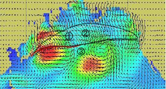
The wind on the earth changes greatly with location or seasons (when upper left figure is clicked, change of a monthly wind will be seen). As for an example of WCSS calculation on the optimum North America route from Seattle to Yokohama, it is shown as the following.
In the case of using the advantageous wind of the strong low pressure located in the east in Hokkaido on the south, the optimal route is indicated as the figure. Thus, by catching a wind well, the larger energy saving (30%) than the great-circle route (about 23%) is obtained as shown the lower figure, though the cursing distance becomes long.
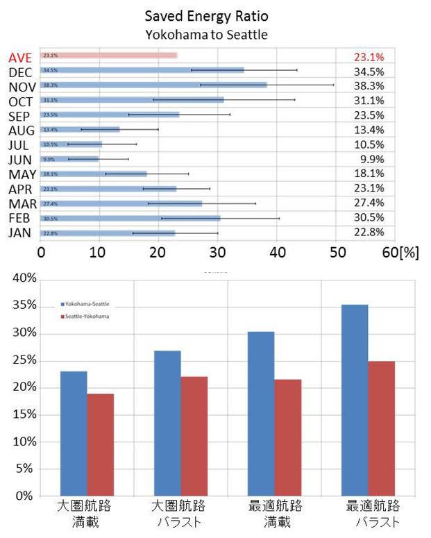
By performing such a simulation for one year, the monthly expected value of the energy-saving rate of a North America route (Yokohama-Seattle) can be calculated as shown in the lower figure). An energy-saving rate increases in winter when westerlies become strong. Thus, like the existing ship, with westerlies or a trade-winds belt, even if one side is advantageous, a reverse route may become disadvantageous on a simple both-way route.
Therefore, the ship's routing that obtains a suitable season and the property of the wind for every ocean space on a global scale becomes very important.